 +86-13646196162
 info@hysonindustry.com




 русский
 عربى



Ring Lock Scaffolding Parts: Component Specs, Tolerances and Buying Guide
 2026.10.16
Content
- 1 Ring Lock Scaffolding Parts at a Glance
- 2 Vertical Standards: Rosette Spacing Sets the Whole Grid
- 3 Ledgers, Wedges and Rosettes: The Connection Carries the Load
- 4 Diagonal Braces: The Part That Keeps a Bay Square
- 5 Jack Bases, U-Heads and the Bottom of the Load Path
- 6 Platforms, Toe Boards and the Accessories Most Orders Forget
- 7 Steel Grade, Galvanizing and Tolerances: What to Check on Delivery
- 8 Buying Ring Lock Parts: A Short Checklist Before You Order
Three containers of ring lock scaffolding arrived on a Monday. By Wednesday the site crew had rejected two of them — not because the steel was thin or the galvanizing patchy, but because the ledger blades would not seat in the rosettes of the standards already standing on site. On paper it was "the same system". In the hand, it was scrap.
That is the daily reality of buying ring lock scaffolding parts. The system looks universal, but the geometry is proprietary: rosette spacing, slot width, blade profile and wedge thickness differ between manufacturers, and parts from two different supply chains rarely lock together. Compatibility comes before price and before lead time. What follows is a part-by-part look at what each component does, which dimension decides whether it fits, and what to check before a purchase order is signed.
Ring Lock Scaffolding Parts at a Glance
A ring lock frame assembles from seven functional groups. Suppliers sell them separately, and all of them have to come from the same geometry family.
| Component | Job it does | Specification that decides fit |
|---|---|---|
| Vertical standard | Carries vertical load, sets lift height | 48.3 x 3.2 mm tube, Q355B, rosettes every 500 mm |
| Ledger | Links standards at each level | Bay lengths 0.73–3.07 m, forged blade ends |
| Diagonal brace | Keeps bays square, resists lateral load | 48.3 x 2.5 mm tube, sized to bay width and lift |
| Wedge pin | Locks the blade into the rosette | Drop-forged, matched to rosette slot width |
| Base jack | Levels the frame, transfers load to ground | 38 mm screw, 150 x 150 mm plate, 300 mm adjustment |
| U-head or fork head | Supports beams and formwork at the top | 150 x 150 mm plate; fork head for H20 timber |
| Platform and edge protection | Working deck and fall protection | 320 mm plank, 150 mm toe board |
Together with ties, ladders and toe boards, those groups make up the whole bill of materials — provided every line is ordered against one manufacturer's rosette pattern.
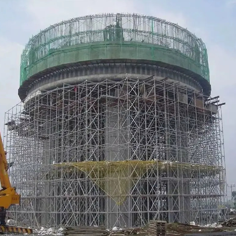 Hot-Dip Galvanized Ringlock Scaffolding for Heavy InfrastructureModular ringlock system with rosette-style wedge locking, Q345B steel, hot-dip galvanized finish, and 8-way connections for bridge and industrial support.View Product →
Vertical Standards: Rosette Spacing Sets the Whole Grid
The vertical standard is the load-bearing member. The common ring lock size is 48.3 mm outside diameter with a 3.2 mm wall in Q355B steel, with a spigot at one end for splicing and rosettes welded at fixed intervals. Heavy shoring versions step up to 60.3 mm tube.
On most systems the rosette pitch is 500 mm, and standard lengths run from 0.5 m to 3.0 m in 500 mm increments. That single number sets the length of every ledger, the size of every brace, the spacing of every plank and the height of every lift. Change the module and the whole catalogue changes with it.
What to measure when the first pallet lands
- Rosette pitch measured between weld centres, not from the tube end.
- Slot width and blade thickness together — a 10 mm slot with a 9.5 mm blade is a loose connection.
- Tube diameter and wall thickness with a calliper; 48.0 mm tube gets sold as 48.3 mm more often than anyone admits.
- Spigot length and pin hole position, because a short spigot turns a splice into a decorative joint.
Ledgers, Wedges and Rosettes: The Connection Carries the Load
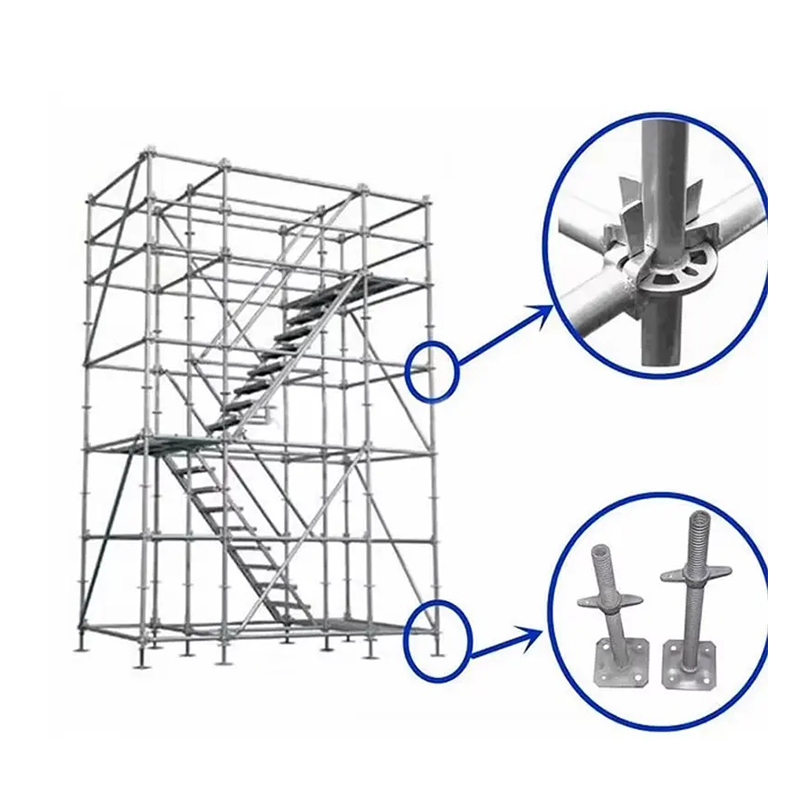
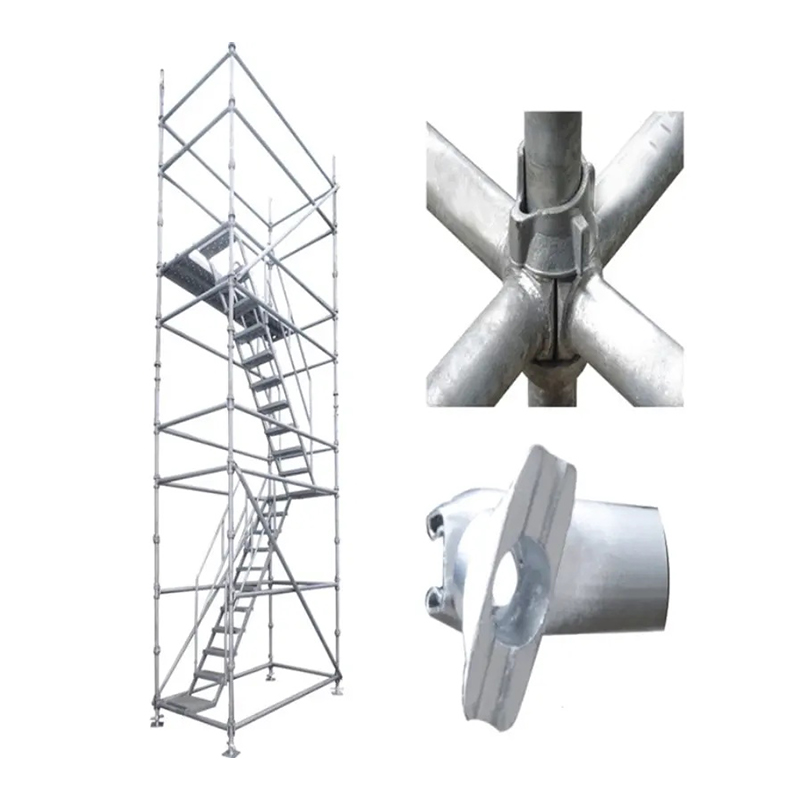
A ring lock ledger is not bolted. Its forged blade drops into a slot in the rosette and a wedge pin is driven down to lock it: one hammer blow, no loose couplers. The rosette normally carries eight slots at 45 degrees, so ledgers meet at right angles and braces run off diagonally from the same node.
Standard bay lengths are 0.73, 1.09, 1.40, 1.57, 2.07, 2.57 and 3.07 m, and a 2.07 m bay with a 2.0 m lift is the most common working configuration. Ring lock is only one of the four main scaffold system families; the others share the modular idea, but only ring lock standardises the node itself. Wedges are consumables, so order 5–8% spares rather than discovering the shortage at the top lift. When inspecting, look at the blade-to-tube weld — cast blades crack at the shoulder, forged blades bend first and can be spotted before they fail.
Diagonal Braces: The Part That Keeps a Bay Square
Two standards and two ledgers make a hinge. The brace is what turns it into a triangulated structure. Bay braces are usually 48.3 x 2.5 mm tube with fixed or swivel heads sized to the bay width and lift height together — a 2.07 x 2.0 m brace will not fit a 2.57 m bay.
Design practice is normally full bay bracing in the bottom lift, then braced bays at intervals across each face, with plan bracing at tie levels. The exact pattern belongs to the designer's drawing, but the part that goes wrong is usually the order: ledgers counted, braces forgotten.
- Confirm the brace matches both bay length and lift height, not just the bay.
- Check head pin diameter against the rosette slot; undersized pins vibrate out.
- Reject bowed tubes — a 20 mm bow pulls the bay out of plumb while it is being locked.
Jack Bases, U-Heads and the Bottom of the Load Path
An adjustable base jack is a solid screw, commonly 38 mm diameter and 600 mm long, welded to a 150 x 150 x 8 mm plate with roughly 300 mm of usable adjustment. That adjustment is for levelling, not for extending the frame: capacity falls as the screw extends, so keep the exposed thread short and bear the plate on a sole board that spreads the load.
The same logic applies at the top. U-heads with 150 x 150 mm plates carry beams and formwork, while fork heads hold H20 timber beams in position. Both drop into the top of a standard or onto a spigot, so the head must match the tube, not only the load. On delivery, check the plate weld, roll the screw on a flat surface for straightness, and reject painted threads — paint hides cracks and seizes the nut.
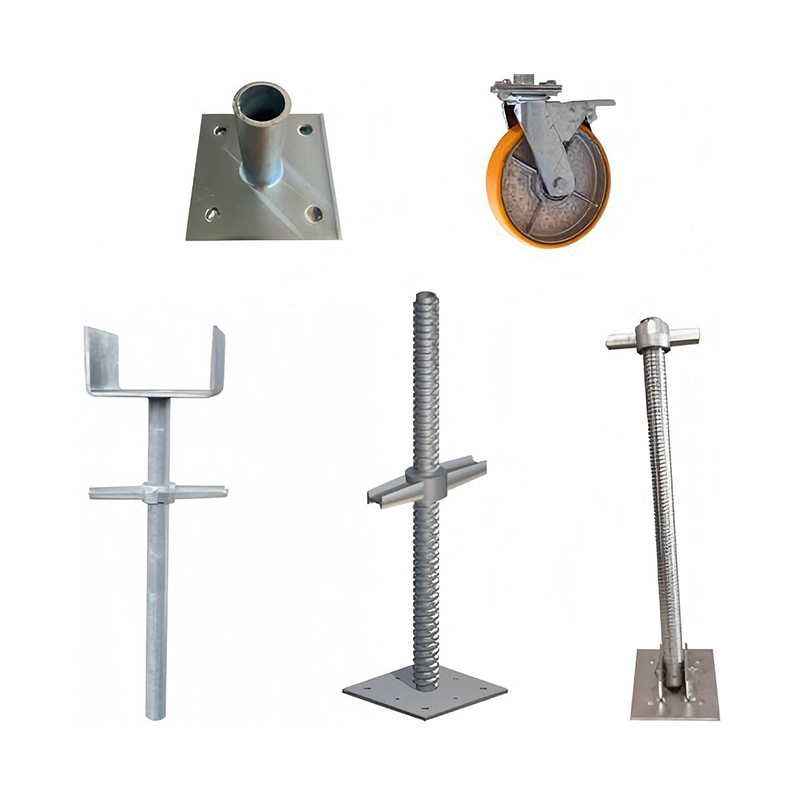 Adjustable Base Jack for Scaffolding and Formwork SupportThreaded base jack levels uneven ground, adjusts 50–300 mm, supports 50–100 kN, and fits disc-lock, formwork, and standard scaffolding systems.View Product →
Platforms, Toe Boards and the Accessories Most Orders Forget
Steel planks are usually 320 mm wide with hooks that drop over the ledger, and each one weighs 12–18 kg, which makes them a manual-handling decision as much as a structural one. Toe boards are 150 mm high; guardrail posts and double couplers form the edge protection. Side brackets widen the platform without adding standards, and that is where much of the productivity gain in a ring lock system actually comes from.
The parts that delay handover are almost never the main members. They are the small ones: spigot pins, safety clips, collars, ladder units, tie couplers and fork heads. Build the bill of materials item by item, one line per component, and the shortage disappears.
 Fork Head Support for Formwork Ribs and BeamsFork head supports formwork ribs and beams with ±0.5 mm threaded adjustment, Q235/Q345 steel, and hot-dip galvanized finish for large-scale formwork.View Product →
Steel Grade, Galvanizing and Tolerances: What to Check on Delivery
Two orders can look identical on a loading list and behave very differently after two years outdoors. Grade, wall thickness and finish explain almost all of the difference.
| Finish | Typical coating | Behaviour outdoors | Cost note |
|---|---|---|---|
| Hot-dip galvanised | 55–85 µm (EN ISO 1461) | Longest service life, standard for rental fleets | Adds 4–6% to part weight |
| Pre-galvanised | 15–25 µm | Short to medium life, weak in coastal air | Cut edges and welds unprotected |
| Painted | 40–80 µm epoxy or alkyd | Needs rework within a few years | Lowest upfront, chips at impact |
| Bare or oiled | None | Immediate use only | For parts to be painted later |
Standards give the reference points: EN 12810 and EN 12811 for system scaffolds, BS 1139-5 in the UK market, with working platforms commonly designed to load class 3 (200 kg/m²) or class 4 (300 kg/m²). Hyson states that its scaffolding production follows ISO 9001, BS 1139 and EN 74, with welding to AWS and EN procedures. Then check three physical things: wall thickness at the tube end, straightness over the full length, and weld spatter inside the tube that will chip off onto the platform below.
Buying Ring Lock Parts: A Short Checklist Before You Order
- Verify rosette geometry first — pitch, slot width and blade thickness — against the system already on site.
- Ask for mill certificates and a galvanizing thickness report, not a photograph of a pallet.
- Confirm the grade part by part: standards and ledgers in Q355B, planks and toe boards often in Q235.
- Agree a spare ratio for wedges, pins and clips before shipping, not after the first delivery.
- Check packing and loading: bundles by length, one loading plan per container, weight verified against the invoice.
If you would rather not run that checklist against a supplier you have never audited, send us your bay sizes, lift heights and load class and we will come back with a part list and a drawing check.
Ring lock scaffolding parts are simple objects inside an unforgiving system. Match the geometry, match the grade and finish, and count the small parts in the same order — those three things decide whether a delivery gets erected or returned.
Hyson manufactures ringlock scaffolding and its accessories in Nantong, China, alongside steel formwork and heavy steel structures, in a 15,000 m² plant with laser cutting, bending and certified welding under one roof. Parts are supplied hot-dip galvanised, and incoming orders are checked against the customer's existing rosette pattern before production starts. Fifteen years of experience and long-running supply to large infrastructure contractors says something about the drawing office — but the specification on your drawing is still the thing that decides the order.


- Location
- Group 3, Fangzhuang Village, Rucheng Subdistrict, Rugao City, Nantong, Jiangsu, China
- Follow us
- Phone
- +86-13646196162
- info@hysonindustry.com
